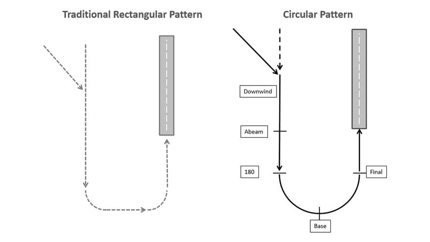
So why do General Aviation aircraft fly a rectangular shape circuit at an airfield and military aircraft usually an oval circuit with circular ‘ends’?
Whatever the reason, the AOPA Air Safety Institute and University of North Dakota, a well-known aviation college, has announced a study into the use of a continuous turning approach or ‘circular circuit’ (‘pattern’ in American English) as an alternative to the traditional box or rectangular traffic pattern.
The study has come about after the NTSB, which investigates air accidents in the US, again named ‘In-flight Loss of Control’ as a major cause of accidents to GA pilots. NTSB officials in a round-the-table discussion with industry came up with the idea that AOPA and UND get together to explore how simple procedural and training methodology changes in the landing circuit might improve safety and reduce loss-of-control accidents.
The suggestion is that a continuous turn from the downwind leg to final may offer increased stability, reduced pilot workload, and a constant bank angle, helping pilots better manage angle-of-attack changes.
It’s also thought that there’s less chance of overshooting a runway during that final base-to-final turn. Many stall/spin accidents have occurred during this low level turn, some because of a too steeply banked turn to get inline with the runway.
“It’s too early to say for sure if the continuous turn to final method will be a safer, more stabilised way to land,” said George Perry, senior vice president of AOPA’s Air Safety Institute.
“But what we do know is General Aviation has been flying the rectangular pattern [circuit] for decades, and based on substantial loss-of-control accident data in the landing pattern, we believe it’s time to conduct research to determine if there is a potentially safer alternative.
“The U.S. military, commercial airlines, and many airline ab initio programs already utilise the continuous approach turn as the standard to support safe landing pattern operations. We should determine which is safer for General Aviation, and this study will help us find the answer.”
The research will consist of flight data analysis to evaluate differences between the circular circuit and the rectangular circuit, according to UND which is carrying out the study.
“Variables that will be analysed include bank angle, airspeed, and runway overshoot,” said Lewis Archer of UND’s aviation dept. “Although the study is in its early phases, and it’s far too soon to draw any definitive conclusions, the new procedure has already been studied and practiced by a select group of UND instructor pilots and initial data collection has been going quite well.”
AOPA in the US reports that the study results should be available in early 2017.
LINKS
AOPA Air Safety Institute
University of North Dakota


6 comments
The “oval” circuit is not so alien to General Aviation as this article would suggest – I have not come across any organisation providing multi-engine training that does not teach visual oval circuits.
If oval circuits were to be used for initial pilot training in single engine aircraft then the ridiculously large rectangular circuits that are so common would disappear. Student pilots would then get more landing practice and less cross-country flying in a typical circuit flying lesson.
I would prefer an oval circuit pattern but the different climb performance and speed of aircraft might make for widely different sized circuits. As I fly a sport biplane the oval style is far superior.
From what I remember the rectangular circuit was intended to allow aircraft with marginal power/rate of climb to avoid climbing whilst in the turn, and I suppose they maintained the rectangular pattern to avoid confusion at the end of the downwind leg
The gliding circuit “cuts the corner” of the rectangular circuit by adding a diagonal leg between downwind and base. This allows continuous observation of the landing area and enables adjustment of the flight path to allow for under and overshooting. It’s a very good method.
I think the rectangular power circuit is stupid. If the engine were to fail at the end of the downwind leg, a light single aircraft would not reach the airfield, hence this type of circuit invites stall/spin accidents and unnecessary landouts.
A study of the circuit patterns proscribed for GA in many European countries, shows that they are irregular: noise abatement. There are not a lot of European airfields frequented by ‘grass roots’ level traffic that would tolerate a switch to a perfectly or even approximately ovoid circuit.
As the article said, oval is the standard circuit for airlines. In detail, take off, climb to 1000′, climbing turn onto downwind, power reduction at 1200′ to allow level off at 1500′. Fly double drift downwind. Flaps, gear downwind, checks. Stopwatch abeam touchdown. 3 secs/100′ so 45 secs±along track wind component. Flaps 10 secs short of turn, turn on time while allowing speed to bleed off with extra drag then descend on flap speed. Look for runway. If high or on slope, final flap. Adjust RoD and RoT to achieve stable final.